

Blog
Industrial pellet systems operate under continuous mechanical load ranging from 18–22 hours per cycle in typical biomass plants.
Stable output depends on die stress distribution, feed particle geometry, and thermal friction control accuracy within ±3°c tolerance.
Failure rates increase significantly when moisture deviation exceeds 2% from calibrated feedstock baseline conditions.
This guide presents structured troubleshooting logic supported by measurable engineering parameters and failure response data.
Get professional poultry farm construction guidance, equipment selection solutions, and the latest price lists, whatsApp to +8618830120193, +2348111199996, or click to learn more.
 Group Equipment")
Pellet Machine Working Principle Overview
Pellet machines convert lignocellulosic biomass into dense fuel through mechanical compression and friction induced thermal softening.
Lignin activation begins at approximately 85°c, enabling particle bonding without external binders under sufficient axial pressure.
Torque transmission from gearbox to die typically ranges between 180–260 nm in mid scale industrial systems.
Data is for reference only.Swipe horizontally to view full table.
Operational stability depends on uniform radial load distribution across die holes and consistent friction coefficient maintenance.
Common Pellet Machine Failure Types
Mechanical failure patterns correlate strongly with abrasive feedstock composition and uneven load cycling frequency.
Gearbox fatigue often initiates after 600–900 operational hours under unstable torque conditions.
Data is for reference only.Swipe horizontally to view full table.
Thermal overload cases are frequently linked to insufficient lubrication film thickness below 0.02 mm boundary threshold.
Raw Material Quality Impact Science Section
Biomass particle morphology directly affects compression resistance and pellet density formation kinetics.
Irregular particle geometry increases void ratio, reducing final structural integrity by up to 12–18% in extreme cases.
Data is for reference only.Swipe horizontally to view full table.
Lignin softening threshold varies between 78–92°c depending on cellulose crystallinity index.
Step 1 Machine Startup Diagnosis
Startup phase instability often indicates abnormal motor inductance response or gearbox backlash beyond design tolerance.
Current spike above 65a during acceleration suggests rotor resistance imbalance or feeder overload.
Data is for reference only.Swipe horizontally to view full table.
Electromagnetic torque delay greater than 0.3 seconds usually correlates with capacitor degradation in control circuits.
Step 2 Die And Roller Inspection
Wear progression on die surface typically follows exponential abrasion curve influenced by silica content in raw biomass.
Surface micro cracks exceeding 0.1 mm depth significantly accelerate material fragmentation instability.
Data is for reference only.Swipe horizontally to view full table.
Misalignment above 0.12 mm radial offset increases friction heat generation by approximately 14–22%.
Step 3 Lubrication System Control
Lubrication failure is a primary contributor to bearing thermal fatigue and micro pitting formation.
Viscosity breakdown occurs rapidly when operating temperature exceeds 72°c continuously.
Data is for reference only.Swipe horizontally to view full table.
Inadequate film separation reduces bearing lifespan by up to 35% under cyclic load conditions.
Step 4 Temperature And Pressure Regulation
Thermo mechanical coupling instability leads to uneven pellet expansion during cooling phase.
Pressure fluctuation above 3 MPa variation causes density stratification inside pellet core structure.
Data is for reference only.Swipe horizontally to view full table.
Rapid cooling gradients above 2.5°c/min may induce micro fractures in lignin bonding matrix.
Step 5 Output Consistency Adjustment
Production instability is typically caused by feeder slip ratio deviation exceeding 5% under variable load conditions.
Uneven residence time inside compression chamber leads to inconsistent pellet density distribution.
Data is for reference only.Swipe horizontally to view full table.
Material backflow phenomenon occurs when die resistance exceeds feeder thrust capacity threshold.
Maintenance Strategy And Prevention Methods
Predictive maintenance reduces unscheduled downtime through vibration monitoring and thermal signature tracking.
Systematic inspection intervals improve gearbox and bearing service life consistency.
Hopper contamination level maintained below 1.5% foreign particles
Die hole cleaning cycle every 120 operating hours
Bearing replacement threshold at 900–1200 hours
Motor insulation resistance above 5 MΩ baseline
Vibration amplitude controlled under 4.5 mm/s
Frequently Asked Questions
Q1: Why does pellet machine produce uneven pellets?
A1: Uneven pellet geometry is typically caused by die wear exceeding 0.4 mm or inconsistent feeder torque stability.
Density variation often correlates with 3–5% moisture fluctuation range.
Q2: What causes frequent die blockage?
A2: Blockage is mainly triggered by particle oversize above 4 mm or sudden moisture spike beyond 15%.
Thermal softening imbalance reduces extrusion continuity.
Q3: How often should rollers be replaced?
A3: Rollers should be replaced after 800–1200 operating hours depending on silica abrasion intensity and load cycling frequency.
Hardness drop below hrc 55 indicates structural fatigue onset.
Taiyu (HK) Group - One Of China Largest Pellet Machine Manufacturer
Industrial pellet machine deployed in biomass densification lines handling 2–8 ton/h capacity configurations with automated feeding synchronization.
Global factory direct manufacturing system integrates machining tolerance control within ±0.02 mm precision standard.
Poultry equipment and biomass pellet system engineering based on modular skid mounted installation architecture.
Turn key engineering covers crushing, drying, pelleting, cooling, and packaging integration with plc-based control logic.
International supply chain ensures gearbox, die, and bearing sourcing stability under continuous 24/7 production environments.
Contact Us To Received Your Customized Poultry Farm Plan
Headquarters And Branchs
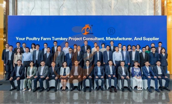
Hong Kong Headquarter Management Team
Hong Kong Headquarter Taiyu Industrial Group CO., LTD
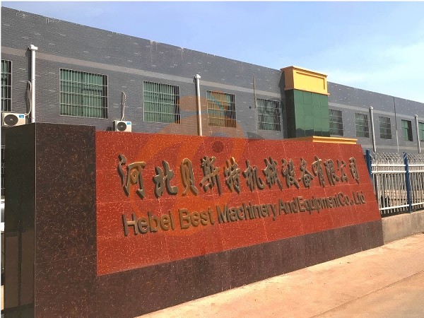
China Hebei Best Machinery And Equipment CO., LTD
Nigeria Vanke Machinery And Equipment CO., LTD
Tanzania Best Machinery And Equipment CO., LTD
Ethiopia Best Hebei Machinery Manufacturing PLC
Reception /24 WhatsApp NO. : +8618830120193
FAQ
What Feeding System Standards Are Required For Pellet Machine In Poultry Chicken Feed Production Lines?
Feeder capacity is designed at 1.2–2.5 tons per hour depending on raw material density.
Flow consistency deviation is maintained within ±2% for uniform pellet quality output.
What Maintenance And Wear Part Replacement Standards Apply To Pellet Machine?
Bearing replacement intervals typically occur every 12–18 months under continuous operation.
Gearbox oil change frequency is maintained at 1000–1500 operating hours for system reliability.
What Safety Protection Systems Are Integrated In Pellet Machine For Poultry Chicken Feed Production?
Emergency stop response time is maintained within 0.5–1.0 seconds for operational safety.
Vibration monitoring limits are set at 4.5–6.0 mm/s to prevent mechanical failure.
Message
Products recommended
 HK Headquarter Offers EU-standard Poultry Farm Solutions, Manufacture Poultry Farm Equipment1. Continuous communication with the EU and the US
2. China, Nigeria, Ethiopia, Tanzania branch companies and factories
3. The products’ quality is customized for local poultry farms
4. Poultry cage and poultry farm equipment stock for sale
5. 24 online reception Whatsapp NO. : +8618830120193,contact us to get full informationRead More China Branch Offer Poultry Farm Business Plan, Manufacture Poultry Farm Equipment1. Address: Flat/RM 2416, 24/F, Runxing Building, Youyi Nan Street, Shijiazhuang City, Hebei Province, China
2. Poultry cage and poultry farm equipment factory and stock for sale
3. Customized for local poultry farms
4. Quality and design are based on Euro
5. 24 online reception Whatsapp NO. : +8618830120193Read More Nigeria Branch Offer Poultry Farm Business Plan, Manufacture Poultry Farm Equipment1. Address: After Sinoma Office, 200 Meters Near Danco Filling Station, Lagos/Ibadan Expressway, Lagos State, Nigeria
2. Poultry cage and poultry farm equipment factory and stock for sale
3. Customized for Nigerian poultry farms
4. Quality and design are based on Euro
5. 24 online reception Whatsapp NO. : +8618830120193Read More Ethiopia Branch Offer Poultry Farm Business Plan, Manufacture Poultry Farm Equipment1. Address: WR93+FQ2, Addis Ababa, Ethiopia
2. Poultry cage and poultry farm equipment stock for sale
3. Customized for Ethiopian poultry farms
4. Quality and design are based on Euro
5. 24 online reception Whatsapp NO. : +8618830120193, contact us to get price listRead More Tanzania Branch Offer Poultry Farm Business Plan, Manufacture Poultry Farm Equipment1. Address: No.8, Sova Road, Msufini, Mlandizi, Kibaha, Pwani, Tanzania
2. Poultry cage and poultry farm equipment factory and stock for sale
3. Customized for Tanzanian poultry farms
4. Quality and design are based on Euro
5. 24 online reception Whatsapp NO. : +8618830120193Read More Fully Automatic H Type Layer Chicken Cage1. 30,000-100,000+ layers/house chooses it, Poultry farmers can achieve an egg production rate of 96-98%
2. A significant improvement over the 85-90% typically seen in manual systems
3. A typical poultry farm can expect a 30-40% reduction in labor costs due to the automation
4. Each feeding line efficiently supplies feed to around 100,000 hens per 30 mins
5. Reception /WhatsApp NO. : +8618830120193Read More Fully Automatic A Type Layer Chicken Cage1. 10,000-50,000 layers/house chooses it
2. Cleaner egg collection reduces breakage by 0.5%
3. Improved hygiene helps reduce mortality rate to <3%
4. 1–2 technicians can handle 15,000–30,000 birds
5. Reception /WhatsApp NO. : +8618830120193Read More Semi Automatic H Type Layer Chicken Cage1. 1,00-20,000 layers/house chooses it
2. Nipple drinkers flow 30–60 ML / min
3. Hot-dip galvanized (typical coating ≥ 275 g/m²)
4. Reduce ammonia by ~ 35–40%
5. Reception /WhatsApp NO. : +8618830120193Read More Semi Automatic A Type Layer Chicken Cage1. 1,00-20,000 layers/house chooses it, no rust for 10 years, no deformation for 15 years
2. Chickens live comfortably, you can raise them with peace of mind
3. Save water, save money—efficiency you can measure
4. Improve environment quality, and increase egg production rate
5. Reception /WhatsApp NO. : +8618830120193Read More


By clicking 'Allow All', you agree to the storage of cookies on your device to enhance site navigation, analyze site usage and assist with our marketing efforts.