

Blog
Pralson feeder system maintenance ensures stable mechanical feed delivery across poultry production lines with controlled performance output levels for continuous farming operation stability.
Auger-driven transport mechanism regulates consistent feed flow using motor torque transmission and standardized rotational speed parameters for uniform distribution across feeding lines.
Engineering maintenance procedures reduce mechanical wear rate, minimize friction loss, and extend operational lifespan of automated feeding equipment under long-term production conditions.
Feed distribution uniformity improves poultry flock growth performance, stabilizes feed conversion ratio values, and reduces feed waste percentage across commercial farming systems.
Structured inspection routines maintain electrical stability, mechanical efficiency, and long term system reliability performance across all Pralson feeder operational environments.
Get professional poultry farm construction guidance, equipment selection solutions, and the latest price lists, whatsApp to +8618830120193, +2348111199996, or click to learn more.
 Group Equipment")
System Function and Operational Role
A Pralson feeder system operates through synchronized mechanical transmission between motor, auger, and feed pan units.
The feeding line architecture is designed for scalable poultry house layouts, supporting modular installation across commercial farming environments.
Feed output per cycle is controlled through system calibration based on bird age stage and feed density formulation, ensuring consistent rationing across all distribution points.
Data is for reference only.Swipe horizontally to view full table.
Mechanical Working Principle Of Pralson Feeder
The Pralson feeder system converts electrical energy into controlled mechanical rotation through a motor gearbox assembly, producing stable torque transfer to the auger shaft for continuous feed movement.
The auger generates a spiral conveying action inside the pipe, maintaining steady axial feed displacement with minimal interruption during long feeding cycles.
In practical operation, internal shaft torque stability typically remains within 1.5–2.6 N·m under normal farm loading, ensuring consistent pushing force along extended distribution lines.
Mechanical performance depends on friction balance between feed particles and tube wall, where excessive resistance may increase motor current demand by 8–12%.
Proper structural alignment ensures smooth rotation, reduced vibration, and stable feed propulsion under continuous poultry production conditions, maintaining predictable delivery performance across long operational cycles.
Feed Flow Engineering Analysis
Feed flow inside the system is governed by granular material dynamics, where particle interaction, density distribution, and moisture absorption directly affect transport efficiency.
Feed processing quality strongly determines whether material moves in uniform flow or develops localized blockage zones inside the auger tube.
Data is for reference only.Swipe horizontally to view full table.
Cleaning and Contamination Control System
Hygienic control in feeding systems directly influences biological safety and feed integrity.
Residual feed accumulation inside transport and dispensing areas creates microbial activity zones if not removed within defined sanitation cycles.
System cleaning is structured based on exposure intensity and contamination probability across different components.
Data is for reference only.Swipe horizontally to view full table.
Motor Load and Electrical Performance Control
Motor operation is influenced by feed resistance, mechanical load distribution, and line length configuration.
Electrical stability ensures consistent torque delivery during feeding cycles.
Power consumption varies depending on system workload intensity and mechanical resistance conditions within the auger system.
Data is for reference only.Swipe horizontally to view full table.
Mechanical Wear and Replacement Cycle
Mechanical wear develops gradually due to continuous contact between feed particles and auger surfaces.
Material abrasion rate is influenced by feed hardness, mineral content, and operating hours accumulation.
Component replacement cycles are determined based on fatigue thresholds and structural deformation limits.
Data is for reference only.Swipe horizontally to view full table.
Lubrication Engineering and Friction Control
Lubrication reduces mechanical resistance in rotating assemblies and stabilizes long term torque transmission efficiency.
Proper grease application prevents overheating and reduces bearing stress accumulation.
Friction reduction improves system energy utilization and extends mechanical component lifespan under continuous operation cycles.
Data is for reference only.Swipe horizontally to view full table.
Feeding Efficiency and System Output Metrics
System efficiency is evaluated through feed utilization performance, energy consumption balance, and output uniformity across feeding cycles.
Feed conversion stability is directly linked to mechanical precision and distribution consistency across poultry houses.
Data is for reference only.Swipe horizontally to view full table.
Seasonal Environmental Impact on Feeder Operation
Environmental variation affects feed physical properties and mechanical transport behavior inside the system.
Moisture accumulation increases cohesion forces between particles, influencing flow resistance.
Temperature variation also affects material expansion and mechanical tolerance stability.
Data is for reference only.Swipe horizontally to view full table.
Maintenance Execution Workflow
Maintenance execution is structured into periodic operational cycles designed to ensure system stability and reduce unexpected downtime events.
Inspection timing is distributed across daily, weekly, and monthly schedules depending on system workload intensity.
Data is for reference only.Swipe horizontally to view full table.
Spare Parts Inventory Optimization
Spare parts availability ensures continuous system operation and reduces production interruption risk in large-scale poultry farms.
Inventory structure is designed based on wear frequency, replacement cycle, and failure probability statistics.
Data is for reference only.Swipe horizontally to view full table.
Frequently Asked Questions
Q1: How frequently should pralson feeder systems be inspected?
A1: Daily inspection is required for mechanical flow stability.
Full system evaluation is recommended every 30 operational days including electrical and mechanical performance verification.
Q2: What factors affect feed blockage inside the system?
A2: Feed blockage is primarily influenced by moisture imbalance.
Particle size inconsistency and material cohesion increase under humidity above recommended operational thresholds.
Q3: What is the service lifespan of a pralson feeder system?
A3: Service lifespan typically ranges between 8 to 12 years under standardized maintenance cycles.
Lubrication intervals and scheduled component replacement programs strongly affect total operational lifespan.
Taiyu (HK) Group - One Of China Biggest Pralson Feeder Manufacturer
Pralson feeder system delivers precision-controlled poultry feed distribution with industrial-grade mechanical stability design.
Factory direct production supports global poultry equipment supply chain and standardized engineering manufacturing capacity.
Poultry cage and feeding integration supports turnkey farm construction and large scale agricultural project deployment.
Automated feeding equipment ensures stable mechanical performance under continuous poultry production environments.
Global export service provides installation, commissioning, and technical support for poultry farming systems.
Contact Us To Received Your Customized Poultry Farm Plan
Headquarters And Branchs
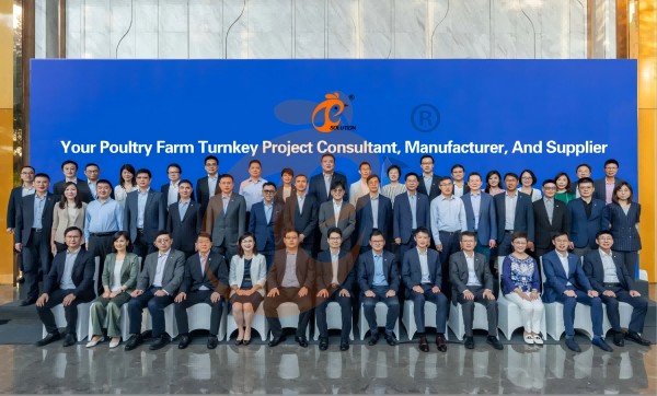
Hong Kong Headquarter Management Team
Hong Kong Headquarter Taiyu Industrial Group CO., LTD
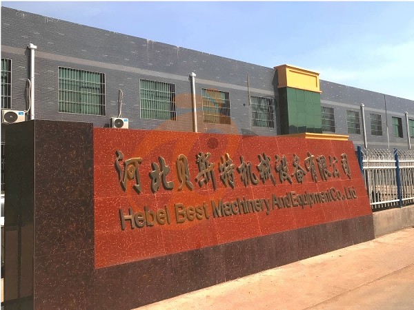
China Hebei Best Machinery And Equipment CO., LTD
Nigeria Vanke Machinery And Equipment CO., LTD
Tanzania Best Machinery And Equipment CO., LTD
Ethiopia Best Hebei Machinery Manufacturing PLC
Reception /24 WhatsApp NO. : +8618830120193
FAQ
What Performance Advantages Does Plasson Poultry Equipment Provide In Poultry Chicken Farming Efficiency?
Labor requirement decreases by 50%–65% through automated water delivery systems.
Disease transmission risk is reduced by 35%–55% due to closed drinking environment design.
What Are The Installation Standards For Plasson Poultry Equipment In Poultry Chicken Farms?
Pipeline slope is maintained at 0.3%–0.5% for effective drainage and hygiene control.
Spacing between drinkers is configured at 25–35 cm to ensure equal water access distribution.
What Maintenance Requirements Apply To Plasson Poultry Equipment In Poultry Chicken Production Systems?
Seal inspection intervals are set at 20–30 days to prevent leakage and pressure loss.
Cleaning solution concentration is maintained at 0.03%–0.06% for effective system sanitation.
Message
Products recommended
 HK Headquarter Offers EU-standard Poultry Farm Solutions, Manufacture Poultry Farm Equipment1. Continuous communication with the EU and the US
2. China, Nigeria, Ethiopia, Tanzania branch companies and factories
3. The products’ quality is customized for local poultry farms
4. Poultry cage and poultry farm equipment stock for sale
5. 24 online reception Whatsapp NO. : +8618830120193,contact us to get full informationRead More China Branch Offer Poultry Farm Business Plan, Manufacture Poultry Farm Equipment1. Address: Flat/RM 2416, 24/F, Runxing Building, Youyi Nan Street, Shijiazhuang City, Hebei Province, China
2. Poultry cage and poultry farm equipment factory and stock for sale
3. Customized for local poultry farms
4. Quality and design are based on Euro
5. 24 online reception Whatsapp NO. : +8618830120193Read More Nigeria Branch Offer Poultry Farm Business Plan, Manufacture Poultry Farm Equipment1. Address: After Sinoma Office, 200 Meters Near Danco Filling Station, Lagos/Ibadan Expressway, Lagos State, Nigeria
2. Poultry cage and poultry farm equipment factory and stock for sale
3. Customized for Nigerian poultry farms
4. Quality and design are based on Euro
5. 24 online reception Whatsapp NO. : +8618830120193Read More Ethiopia Branch Offer Poultry Farm Business Plan, Manufacture Poultry Farm Equipment1. Address: WR93+FQ2, Addis Ababa, Ethiopia
2. Poultry cage and poultry farm equipment stock for sale
3. Customized for Ethiopian poultry farms
4. Quality and design are based on Euro
5. 24 online reception Whatsapp NO. : +8618830120193, contact us to get price listRead More Tanzania Branch Offer Poultry Farm Business Plan, Manufacture Poultry Farm Equipment1. Address: No.8, Sova Road, Msufini, Mlandizi, Kibaha, Pwani, Tanzania
2. Poultry cage and poultry farm equipment factory and stock for sale
3. Customized for Tanzanian poultry farms
4. Quality and design are based on Euro
5. 24 online reception Whatsapp NO. : +8618830120193Read More Fully Automatic H Type Layer Chicken Cage1. 30,000-100,000+ layers/house chooses it, Poultry farmers can achieve an egg production rate of 96-98%
2. A significant improvement over the 85-90% typically seen in manual systems
3. A typical poultry farm can expect a 30-40% reduction in labor costs due to the automation
4. Each feeding line efficiently supplies feed to around 100,000 hens per 30 mins
5. Reception /WhatsApp NO. : +8618830120193Read More Fully Automatic A Type Layer Chicken Cage1. 10,000-50,000 layers/house chooses it
2. Cleaner egg collection reduces breakage by 0.5%
3. Improved hygiene helps reduce mortality rate to <3%
4. 1–2 technicians can handle 15,000–30,000 birds
5. Reception /WhatsApp NO. : +8618830120193Read More Semi Automatic H Type Layer Chicken Cage1. 1,00-20,000 layers/house chooses it
2. Nipple drinkers flow 30–60 ML / min
3. Hot-dip galvanized (typical coating ≥ 275 g/m²)
4. Reduce ammonia by ~ 35–40%
5. Reception /WhatsApp NO. : +8618830120193Read More Semi Automatic A Type Layer Chicken Cage1. 1,00-20,000 layers/house chooses it, no rust for 10 years, no deformation for 15 years
2. Chickens live comfortably, you can raise them with peace of mind
3. Save water, save money—efficiency you can measure
4. Improve environment quality, and increase egg production rate
5. Reception /WhatsApp NO. : +8618830120193Read More


By clicking 'Allow All', you agree to the storage of cookies on your device to enhance site navigation, analyze site usage and assist with our marketing efforts.